Problem
Machining problem to solve
Turbine blades combine:Complex CurvesSuperalloysTight TolerancesExtreme Surface RequirementsTraditional machining:
Case Study
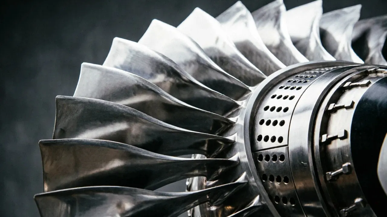
Aerospace Case Study 06 / 15A turbine blade is one of the most technologically advanced components in an aircraft engine.
Case Overview
Problem
Solution
Machine Used
Process
Full Case Article
Item
Details
A turbine blade is one of the most technologically advanced components in an aircraft engine.
Yet its operating environment is among the harshest in engineering.
Hot gas generated by combustion passes through turbine blades.
Located downstream.
HYR CNC developed a dedicated 5-axis turbine blade machining solution.
A turbine blade is not flat.
Traditional machining cannot achieve this efficiently.
The most widely used aerospace superalloy.
Item
What Is 5 Axis CNC Machining?
Inconel 718, Rene 41 and other nickel-based superalloys are widely used.
5-axis machining enables continuous machining of complex airfoil surfaces with high precision.
or better.
Turbine blades are among the most complex and demanding aerospace components.
Their aerodynamic surfaces, high-temperature materials and strict dimensional requirements require advanced 5-axis CNC machining technologies.
With excellent superalloy machining capability, stable dimensional accuracy and aerospace-grade manufacturing solutions, HYR CNC provides reliable and efficient turbine blade machining solutions for global aerospace manufacturers.
Result
| Item | Before | After |
|---|---|---|
| Result 1 | Before optimization | After adopting HYR CNC machining solutions: |
| Result 2 | Before optimization | Profile Accuracy |
| Result 3 | Before optimization | +/-0.010 mm |
FAQ
This page covers turbine blade requirements, machining difficulty, process planning and machine selection.
HYR VMC, HMC and 5-axis machining centers are selected according to material, size, tolerance and contour complexity.
Yes. Send drawings, material, tolerance and production volume for a suitable machining proposal.
Related Products
Related Articles
Similar Case Studies
Unlike ordinary industrial parts, aerospace structural components must satisfy:
A wing rib is one of the most important structural components inside an aircraft wing.
A bulkhead is one of the primary load-bearing structures inside an aircraft.
Request Quote
Send your drawing, material, tolerance, surface finish and production volume. HYR-CNC will recommend the right machine configuration and machining proposal.
Start Machine SelectionRelated Links