HYR hyrcnc Intelligent CNC Solutions

Case Study

Aerospace Case Study 12 / 15

Rocket Engine Component Machining Case Study

Rocket engines are among the most demanding engineering systems ever developed.

rocket engine component machining case studyaerospace cnc machining5 axis aerospace machining
Rocket Engine Component Machining Case Study

Case Overview

Core project data for this machining case.

Industry Aerospace & Space
Product Rocket Engine Components
Material Inconel 718 / Ti-6Al-4V / Copper Alloys / Stainless Steel
Process Forging + CNC Machining + Inspection
Machine Model HYR VMC1165 / HYR 5 Axis Machining Center
Tolerance +/-0.003 mm
Surface Finish Ra0.2-0.4
Application Launch Vehicles / Spacecraft Propulsion / Rocket Engines

Problem

Machining problem to solve
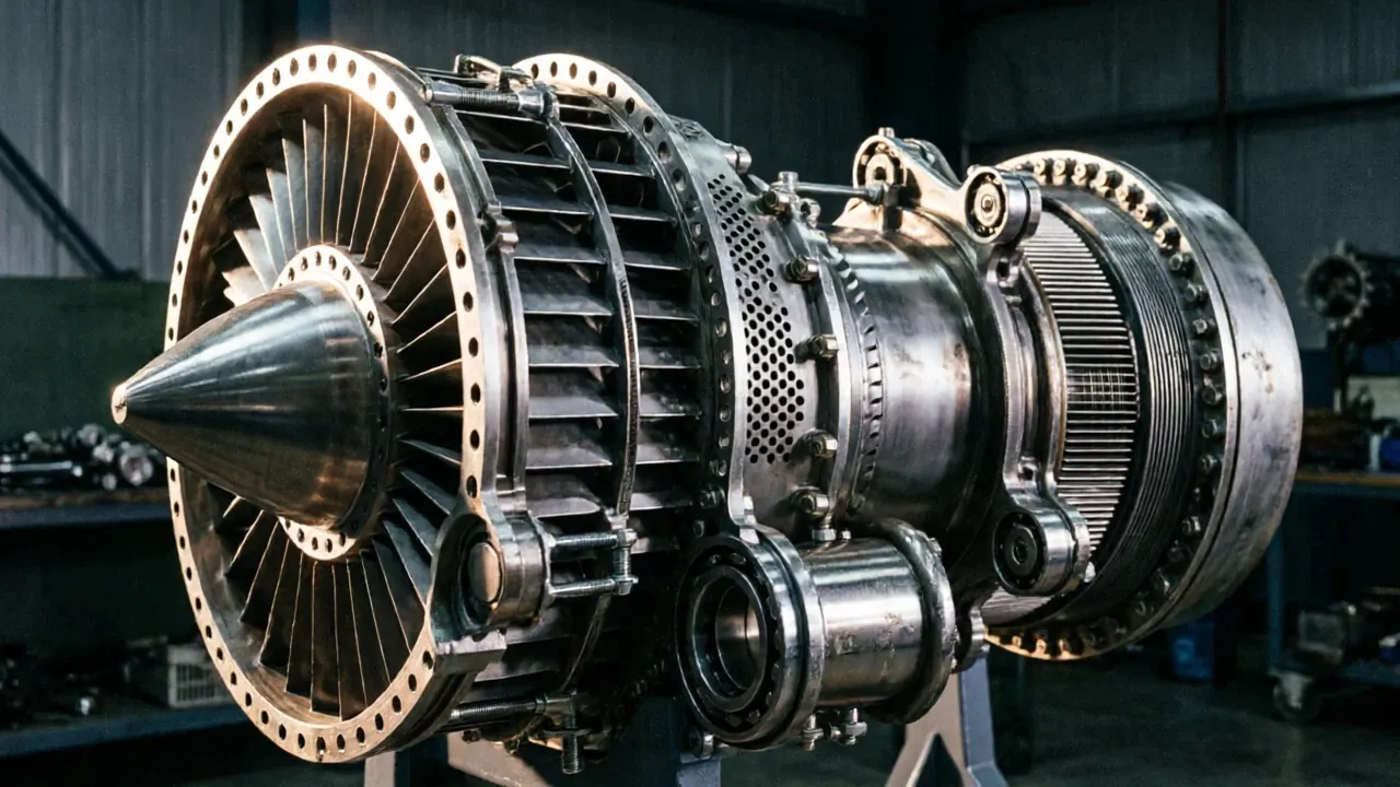
Rocket engine parts combine: Extreme Materials+Complex Geometry+Thermal Requirements+Ultra-High Reliability Rocket engine geometries often include: Curved SurfacesDeep CavitiesMulti-Angle Features Traditional machining: Multiple SetupsLong Cycle TimeAccumulated Error

Solution

HYR-CNC machining plan

The customer manufactures: Launch vehicle propulsion components Rocket engine assemblies Aerospace test hardware Satellite propulsion systems Materials:

Machine Used

Recommended machine configuration

Machine: HYR CNC machining center selected according to aerospace material, part size and tolerance
Process: Rough machining, semi-finishing, 5-axis finishing and inspection based on the document content
Accuracy Control: Rigid fixturing, thermal stability, deformation control and CMM inspection
Cost Method: Published with existing website assets first to keep implementation cost low

Process

Timeline from raw material to inspection.

01 Material preparation
02 Rough machining
03 Semi-finishing
04 5-axis finishing
05 Inspection

Full Case Article

Machining background, difficulty and solution logic.

Quick Facts

Item

Details

Industry Aerospace & Space Product Rocket Engine Components Materials Inconel 718 / Ti-6Al-4V / Copper Alloys / Stainless Steel Manufacturing Process Forging + CNC Machining + Inspection Machine HYR VMC1165 / HYR 5 Axis Machining Center Tolerance +/-0.003 mm Surface Finish Ra0.2-0.4 Application Launch Vehicles / Spacecraft Propulsion / Rocket Engines

Introduction

Rocket engines are among the most demanding engineering systems ever developed.

Unlike aircraft engines: Aircraft EngineContinuous OperationAtmospheric Environment Rocket engines operate under: Extreme Temperature+Extreme Pressure+High-Velocity Exhaust+Short-Duration High Load Every component must survive conditions that can exceed: 3000 degreesC Combustion Temperature Therefore: Rocket Engine Components=High Precision+High Reliability+Mission Critical Parts

What Are Rocket Engine Components?

A rocket engine consists of multiple precision-machined assemblies.

Typical structure: Injector PlateCombustion ChamberThroat SectionNozzleExhaust Expansion Critical machined components include: Injector plates Combustion chamber bodies Nozzle segments Turbopump housings Valve bodies Structural mounting interfaces

Customer Background

HYR CNC developed a dedicated aerospace propulsion machining solution.

The customer manufactures: Launch vehicle propulsion components Rocket engine assemblies Aerospace test hardware Satellite propulsion systems Materials: Inconel 718Ti-6Al-4VCopper AlloysStainless Steel Primary challenges: Heat-resistant materials Complex internal channels Thin-wall structures Tight dimensional control High inspection standards

Why Rocket Engine Components Are Difficult To Machine

Rocket engine parts combine: Extreme Materials+Complex Geometry+Thermal Requirements+Ultra-High Reliability

Challenge 1

Therefore materials must maintain strength under extreme heat.

Extreme Operating Temperatures Combustion temperatures may exceed: 3000 degreesC

Challenge 2

Complex Internal Passages Many rocket components contain: Cooling ChannelsFuel PassagesOxidizer Flow Paths Challenges: Tool accessibility Deep cavity machining Internal geometry control

Challenge 3

Thin-Wall Structures Combustion chambers and nozzles often require: 1-5 mm Wall Thickness Problems: Distortion Chatter Thermal deformation

Challenge 4

Therefore quality requirements are extremely strict.

Safety Requirements A small defect may cause: LeakageCombustion InstabilityMission Failure

Injector Plate

Function: Fuel Distribution+Oxidizer Distribution Requirements: Hundreds of precision holes Tight positional accuracy Excellent surface quality

Combustion Chamber

Function: Fuel CombustionHigh Pressure Gas Generation Requirements: Thermal resistance Structural stability Cooling channel accuracy

Nozzle Component

Function: Gas ExpansionThrust Generation Requirements: Complex profiles Smooth surface finish Geometric consistency

Turbopump Housing

Function: Fuel DeliveryPressure Generation Requirements: Precision bores Concentricity control Reliable sealing interfaces

Inconel 718

Applications: Combustion chambers Turbopump parts Hot-section components Advantages: Heat ResistanceOxidation ResistanceHigh Strength

Ti-6Al-4V

Applications: Structural components Lightweight housings Advantages: High StrengthLow DensityCorrosion Resistance

Copper Alloys

Applications: Regeneratively cooled chambers Heat transfer components Advantages: Excellent Thermal Conductivity

Stainless Steel

Applications: Valve bodies Structural interfaces Advantages: Good StrengthExcellent Manufacturability

Why 5-Axis Machining Is Necessary

Rocket engine geometries often include: Curved SurfacesDeep CavitiesMulti-Angle Features Traditional machining: Multiple SetupsLong Cycle TimeAccumulated Error 5-axis machining provides: Single SetupHigher AccuracyBetter Surface Quality

HYR VMC1165

Suitable for: Injector plates Structural propulsion components Valve housings Advantages: High rigidity Stable precision Excellent heavy cutting performance

HYR 5 Axis Machining Center

Suitable for: Nozzles Combustion chambers Complex aerospace geometries Advantages: Simultaneous multi-axis control High-speed contour machining Superior geometric accuracy

Step 1

Material Preparation Use: Forgings Billets Near-net blanks

Step 2

Rough Machining Remove: 60-80% Material Create: Basic geometry Internal cavities

Step 3

Stress Relief Reduce: Residual StressPart Distortion

Step 4

Semi-Finishing Machine: Cooling passages Mounting interfaces Precision cavities

Step 5

5-Axis Contour Machining Machine: Nozzle profiles Chamber surfaces Complex contours

Step 6

Finish Machining Requirements: Tolerance +/-0.003 mmRa0.2-0.4

Step 7

Critical for aerospace cleanliness requirements.

Deburring and Cleaning Remove: Burrs Loose particles

Step 8

Final Inspection Verify: Dimensions Surface quality Geometric accuracy Material certification

Hole Position Inspection

Requirement: +/-0.01 mm Applications: Injector plates Fuel systems

Surface Finish Inspection

Requirement: Ra0.2-0.4 Applications: Nozzle surfaces Sealing areas

CMM Inspection

Verify: Complete geometry Internal features Assembly compatibility

Material Certification

Verify: Composition Heat treatment Mechanical properties

Results

Item

After implementing HYR machining solutions: Before After Dimensional Accuracy +/-0.010 mm +/-0.003 mm Surface Finish Ra0.8 Ra0.2-0.4 Cycle Time 100% -30% Scrap Rate 1.3% 0.1% Assembly Success Rate Baseline +25% Customer benefits: Better propulsion component reliability Higher manufacturing consistency Reduced production cost Improved delivery performance

HYR VMC1060

Recommended for: Injector plates Valve bodies Small propulsion components

HYR VMC1165

Recommended for: Structural propulsion parts Turbopump housings

HYR 5 Axis Machining Center

Recommended for: Nozzles Combustion chambers Complex aerospace propulsion systems

Related Articles

What Is 5 Axis CNC Machining?

Satellite Housing Machining Case Study Spacecraft Structural Part Machining Case Study Titanium Machining Case Study Inconel Machining Guide

What are rocket engine components?

Rocket engine components include injector plates, combustion chambers, nozzles, turbopumps and structural propulsion assemblies.

Why are rocket engine parts difficult to machine?

Because they combine: Extreme materials Tight tolerances Complex geometries High reliability requirements

What materials are commonly used?

Inconel 718, Ti-6Al-4V, copper alloys and stainless steel.

Why is 5-axis machining important?

5-axis machining enables efficient production of complex propulsion components while maintaining precision and surface quality.

What tolerance is typically required?

or better.

Most rocket engine components require: +/-0.003 mm

Conclusion

Rocket engine components represent some of the most demanding parts in modern aerospace manufacturing.

Their complex geometries, extreme operating environments and stringent quality requirements require advanced CNC machining technologies.

With expertise in aerospace materials, precision machining and complex component manufacturing, HYR CNC provides reliable and efficient solutions for rocket engine component production.

Result

Before and after machining improvement.

ItemBeforeAfter
Result 1Before optimizationAfter implementing HYR machining solutions:
Result 2Before optimizationDimensional Accuracy
Result 3Before optimization+/-0.010 mm

FAQ

Common buyer questions for this case.

What is this aerospace article about?

This page covers rocket engine components requirements, machining difficulty, process planning and machine selection.

Which machines are recommended?

HYR VMC, HMC and 5-axis machining centers are selected according to material, size, tolerance and contour complexity.

Can HYR-CNC support similar aerospace parts?

Yes. Send drawings, material, tolerance and production volume for a suitable machining proposal.

Related Products

Related Articles

Similar Case Studies

More Aerospace machining proof.

Request Quote

Need a similar CNC machining solution?

Send your drawing, material, tolerance, surface finish and production volume. HYR-CNC will recommend the right machine configuration and machining proposal.

Start Machine Selection

Related Links