HYR hyrcnc Intelligent CNC Solutions

Case Study

Aerospace Case Study 05 / 15

Landing Gear Component Machining Case Study

Ti-6Al-4V titanium, 300M steel and 4340 steel are the most common materials.

landing gear component machining case studyaerospace cnc machining5 axis aerospace machining
Landing Gear Component Machining Case Study

Case Overview

Core project data for this machining case.

Industry Aerospace
Product Landing Gear Component
Material Ti-6Al-4V / 300M Steel / 4340 Steel
Process Forging + Heat Treatment + 5 Axis CNC Machining
Machine Model HYR VMC1165 / 5 Axis Machining Center
Tolerance +/-0.005 mm
Surface Finish Ra0.4
Application Commercial Aircraft / Military Aircraft / UAV

Problem

Machining problem to solve

Landing gear machining is challenging because of: High Strength Materials Complex Geometry Strict Safety Requirements Tight Tolerances Traditional machining:

Solution

HYR-CNC machining plan

The customer produces: Main landing gear components Torque links Titanium structural parts UAV landing systems Materials:

Machine Used

Recommended machine configuration

Machine: HYR CNC machining center selected according to aerospace material, part size and tolerance
Process: Rough machining, semi-finishing, 5-axis finishing and inspection based on the document content
Accuracy Control: Rigid fixturing, thermal stability, deformation control and CMM inspection
Cost Method: Published with existing website assets first to keep implementation cost low

Process

Timeline from raw material to inspection.

01 Material preparation
02 Rough machining
03 Semi-finishing
04 5-axis finishing
05 Inspection

Full Case Article

Machining background, difficulty and solution logic.

Quick Facts

Item

Details

Industry Aerospace Product Landing Gear Component Materials Ti-6Al-4V / 300M Steel / 4340 Steel Manufacturing Process Forging + Heat Treatment + 5 Axis CNC Machining Machine HYR VMC1165 / 5 Axis Machining Center Tolerance +/-0.005 mm Surface Finish Ra0.4 Application Commercial Aircraft / Military Aircraft / UAV

Introduction

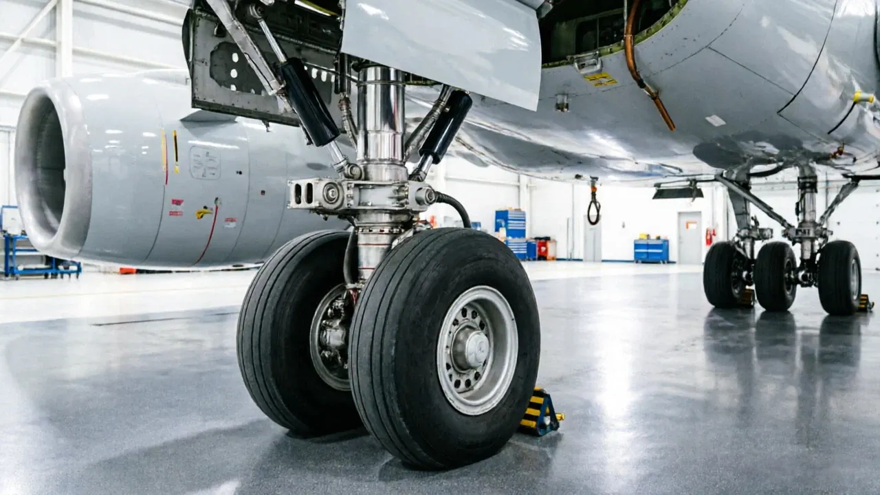
The landing gear is one of the most critical systems of an aircraft.

Its mission appears simple: Take Off Retract Land Safely But in reality: Landing gear components must withstand: Aircraft weight Landing impact Braking forces Side loads Repeated fatigue cycles A single landing may generate: Several Tons of Impact Load Military aircraft: Even Higher Shock Loads and Extreme Conditions Therefore: Landing gear parts are regarded as: One Of The Highest Strength Mechanical Components In Aerospace

Main Landing Gear Components

A complete landing gear system includes:

Main Strut

Function: Support: Aircraft weight Landing loads Ground operations Characteristics: Large Size High Strength Complex Geometry Common materials: Ti-6Al-4V 300M Steel

Torque Link

Function: Prevent: Unwanted Rotation Characteristics: Thin wall Complex contours Multiple bores

Axle

Function: Connect: Wheels Brakes Bearings Requirements: Ultra High Precision Excellent Fatigue Life

Side Stay

Function: Provide: Lateral Support Requirements: High stiffness High fatigue strength

Actuator Housing

Function: Control: Extension Retraction Locking Requirements: Precision bores Leak-free sealing

Customer Background

HYR CNC developed a dedicated landing gear machining solution.

The customer produces: Main landing gear components Torque links Titanium structural parts UAV landing systems Materials: Ti-6Al-4V 300M Steel 4340 Steel Main challenges: Titanium machining Tool wear Large cutting forces Hole accuracy Surface integrity

Why Landing Gear Parts Are Difficult To Machine

Landing gear machining is challenging because of: High Strength Materials Complex Geometry Strict Safety Requirements Tight Tolerances

Challenge 1

Titanium Machining Titanium has: Low Thermal Conductivity Heat Concentration Rapid Tool Wear Consequences: Short tool life Surface damage Low productivity

Challenge 2

Ultra High Strength Steel 300M steel properties: Tensile Strength >1900 MPa Characteristics: Difficult cutting High cutting forces Severe tool wear

Challenge 3

Complex Geometry Landing gear parts often include: Deep pockets Thin walls Multiple bores Complex surfaces Typical structure: Deep Pocket Thin Wall Precision Bore Complex Curves

Challenge 4

Safety Requirements Landing gear failure may lead to: Hard Landing Structural Failure Flight Safety Risks Therefore: Every part requires: 100% Inspection

Ti-6Al-4V

The most widely used titanium alloy.

Advantages: High Strength Low Density Corrosion Resistance Applications: Main struts Torque links Structural components

300M Steel

Known as: Ultra High Strength Steel Applications: Landing gear cylinders Main support structures Advantages: Exceptional strength Excellent fatigue resistance

4340 Steel

Applications: Shafts Axles Connecting structures Advantages: Toughness Wear resistance

Why 5 Axis Machining Is Necessary

Traditional machining: Setup Rotate Setup Rotate Setup Problems: Position errors Longer cycle times Reduced accuracy Modern aerospace machining: 5 Axis CNC One Setup Complete Machining Benefits: Better surface quality Reduced setups Higher precision Improved productivity

HYR CNC Solution

HYR recommends:

HYR VMC1165

Suitable for: Titanium parts Steel landing gear components Travel: 1100 × 650 × 650 mm Advantages: High rigidity Stable cutting Excellent heavy machining

5 Axis Machining Center

Suitable for: Complex Landing Gear Parts Titanium Components Multi Surface Structures Advantages: Multi-angle machining Better surface integrity Higher efficiency

Step 1

Forging Produce: High strength blanks Optimized grain flow

Step 2

Heat Treatment Improve: Hardness Fatigue strength

Step 3

Rough Machining Remove: 60% 80% Material Machine: Profiles Cavities External features

Step 4

Stress Relief Reduce: Residual stresses Thermal deformation

Step 5

Prepare for finishing.

Semi Finishing Machine: Thin walls Deep pockets

Step 6

Finish Machining Requirement: Tolerance +/-0.005 mm Ra0.4 Machine: Bores Interfaces Critical surfaces

Step 7

Improve safety and assembly quality.

Deburring Remove: Burrs Sharp edges

Step 8

Guaranteeing aerospace quality.

Final Inspection Inspect: Dimensions Surface Finish Material Certification CMM Inspection

Quality Inspection

Every landing gear component undergoes strict inspection.

Bore Inspection

Requirement: +/-0.005 mm Inspect: Diameter Roundness Cylindricity

Surface Finish

Requirement: Ra0.4 Inspect: Roughness Surface integrity Tool marks

Fatigue Inspection

Verify: Material properties Crack resistance Structural reliability

Material Certification

Ensuring full traceability.

Verify: Chemical composition Heat treatment Mechanical properties

Results

Item

After adopting HYR CNC machining solutions: Before After Surface Finish Ra0.8 Ra0.4 Dimensional Accuracy +/-0.015 mm +/-0.005 mm Cycle Time 320 min 240 min Tool Consumption High Reduced 35% Scrap Rate 1.5% 0.1% The customer achieved: Better surface integrity Improved dimensional stability Reduced tool wear Lower production costs Higher manufacturing efficiency

HYR VMC850

Recommended for: Aluminum Aerospace Parts UAV Components

HYR VMC1060

Suitable for: Medium Titanium Parts Structural Components

HYR VMC1165

Ideal for: Landing Gear Components Titanium Structures High Strength Steel Parts

Related Articles

What Is 5 Axis CNC Machining?

Aircraft Structural Part Machining Case Study Wing Rib Machining Case Study Bulkhead Machining Case Study Titanium Machining Case Study Thin Wall Aerospace Part Machining

What materials are used in landing gear?

Ti-6Al-4V titanium, 300M steel and 4340 steel are the most common materials.

Why is titanium difficult to machine?

Titanium generates high cutting temperatures and causes rapid tool wear due to poor thermal conductivity.

Why is landing gear machining difficult?

Because it combines: High strength materials Tight tolerances Complex geometries Strict safety requirements

Why use 5 axis machining?

5-axis machining improves accuracy, reduces setups and enables efficient machining of complex aerospace parts.

What tolerance is required?

or better.

Most landing gear components require: +/-0.005 mm

Conclusion

Landing gear components are among the highest value and most demanding parts in aerospace manufacturing.

Their complex geometries, high strength materials and strict safety requirements require advanced CNC machining technologies.

With excellent titanium machining capability, stable dimensional accuracy and aerospace-grade machining solutions, HYR CNC machining centers provide reliable and efficient solutions for landing gear manufacturing.

HYR CNC continues to support global aerospace manufacturers with advanced machining technology and customized aircraft landing system production solutions.

Result

Before and after machining improvement.

ItemBeforeAfter
Result 1Before optimizationAfter adopting HYR CNC machining solutions:
Result 2Before optimizationSurface Finish
Result 3Before optimizationRa0.8

FAQ

Common buyer questions for this case.

What is this aerospace article about?

This page covers landing gear component requirements, machining difficulty, process planning and machine selection.

Which machines are recommended?

HYR VMC, HMC and 5-axis machining centers are selected according to material, size, tolerance and contour complexity.

Can HYR-CNC support similar aerospace parts?

Yes. Send drawings, material, tolerance and production volume for a suitable machining proposal.

Related Products

Related Articles

Similar Case Studies

More Aerospace machining proof.

Request Quote

Need a similar CNC machining solution?

Send your drawing, material, tolerance, surface finish and production volume. HYR-CNC will recommend the right machine configuration and machining proposal.

Start Machine Selection

Related Links