HYR hyrcnc Intelligent CNC Solutions

Case Study

Aerospace Case Study 07 / 15

Compressor Impeller Machining Case Study

The compressor impeller is one of the most critical rotating components inside an aerospace engine.

compressor impeller machining case studyaerospace cnc machining5 axis aerospace machining
Compressor Impeller Machining Case Study

Case Overview

Core project data for this machining case.

Industry Aerospace
Product Compressor Impeller
Material Aluminum 7075 / Ti-6Al-4V / Inconel 718
Process Forging + 5 Axis CNC Machining
Machine Model HYR 5 Axis Machining Center
Tolerance +/-0.003 mm
Surface Finish Ra0.2-0.4
Application Aircraft Engines / Gas Turbines / Turbo Compressors

Problem

Machining problem to solve
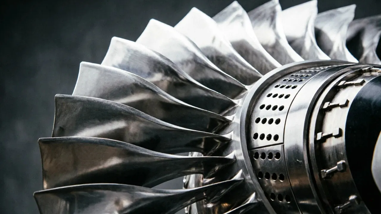
Impellers combine: Thin Blades+Deep Channels+Complex Curves+Tight Tolerances making them one of the most difficult parts in CNC machining. Traditional machining: Multiple SetupsLimited Tool AccessPoor Surface Quality Modern aerospace machining:

Solution

HYR-CNC machining plan

The customer manufactures: Aerospace compressor impellers Turbo machinery components UAV engine parts Materials: 7075 AluminumTi-6Al-4VInconel 718

Machine Used

Recommended machine configuration

Machine: HYR CNC machining center selected according to aerospace material, part size and tolerance
Process: Rough machining, semi-finishing, 5-axis finishing and inspection based on the document content
Accuracy Control: Rigid fixturing, thermal stability, deformation control and CMM inspection
Cost Method: Published with existing website assets first to keep implementation cost low

Process

Timeline from raw material to inspection.

01 Material preparation
02 Rough machining
03 Semi-finishing
04 5-axis finishing
05 Inspection

Full Case Article

Machining background, difficulty and solution logic.

Quick Facts

Item

Details

Industry Aerospace Product Compressor Impeller Materials Aluminum 7075 / Ti-6Al-4V / Inconel 718 Process Forging + 5 Axis CNC Machining Machine HYR 5 Axis Machining Center Tolerance +/-0.003 mm Surface Finish Ra0.2-0.4 Blade Thickness 0.5-3 mm Application Aircraft Engines / Gas Turbines / Turbo Compressors

Introduction

The compressor impeller is one of the most critical rotating components inside an aerospace engine.

Its function: Air IntakeCompressionHigh Pressure AirCombustion Chamber Without efficient compression: No CombustionNo ThrustNo Flight Impeller performance directly affects: Engine efficiency Fuel consumption Pressure ratio Overall engine performance

What Is A Compressor Impeller?

An impeller is a rotating aerodynamic component containing multiple blades.

It converts rotational energy into compressed airflow.

Even microscopic machining errors can affect performance.

As it spins: Mechanical EnergyAir AccelerationPressure Increase Typical rotational speed: 20,000 RPM50,000 RPM100,000 RPM At these speeds:

Open Impeller

Characteristics: Open Blade Structure Advantages: Easier machining Better chip evacuation Applications: Turbochargers Small compressors

Semi-Open Impeller

Features: Higher efficiency Better structural rigidity Applications: Industrial turbines Auxiliary aerospace systems

Closed Impeller

Structure: Blade+Shroud=Closed Impeller Advantages: Highest aerodynamic efficiency Better pressure performance Challenges: Extremely difficult machining

Customer Background

HYR developed a dedicated impeller machining solution.

The customer manufactures: Aerospace compressor impellers Turbo machinery components UAV engine parts Materials: 7075 AluminumTi-6Al-4VInconel 718 Challenges: Thin blades Deep channels Surface finish consistency Long cycle times

Why Impeller Machining Is Difficult

making them one of the most difficult parts in CNC machining.

Impellers combine: Thin Blades+Deep Channels+Complex Curves+Tight Tolerances

Challenge 1

Traditional 3-axis machining cannot efficiently produce these surfaces.

Complex Freeform Surfaces Each blade contains: TwistCurvatureVariable ThicknessAerodynamic Geometry

Challenge 2

Deep Narrow Channels Typical channel depth: 30 mm150 mm Problems: Tool interference Chip evacuation Vibration Tool deflection

Challenge 3

Thin Blade Machining Typical blade thickness: 0.5 mm3 mm Risks: Blade deformation Chatter Burr formation

Challenge 4

Impeller efficiency depends heavily on surface quality.

Surface Finish Requirements Poor finish causes: Airflow TurbulenceEfficiency Loss Typical requirement: Ra0.2-0.4

Aluminum 7075

Advantages: High StrengthLight WeightExcellent Machinability Applications: UAV engines Small compressor systems

Ti-6Al-4V

Advantages: High StrengthCorrosion ResistanceLow Density Applications: Aerospace compressors Military aircraft

Inconel 718

Advantages: High Temperature ResistanceOxidation ResistanceExcellent Fatigue Strength Applications: High-performance turbine systems

Why 5-Axis Machining Is Necessary

Traditional machining: Multiple SetupsLimited Tool AccessPoor Surface Quality Modern aerospace machining: 5 Axis CNCContinuous Tool MotionSingle SetupComplete Geometry Benefits: Higher accuracy Better blade finish Shorter cycle time Improved consistency

HYR 5 Axis Machining Center

Suitable for: Open ImpellersClosed ImpellersBlisksTurbine Components Advantages: Simultaneous 5-axis interpolation High-speed machining Superior surface finish

High-Speed Spindle

Configuration: 15,000 RPM24,000 RPM Benefits: Reduced cutting force Improved finish Better productivity

Step 1

Material Preparation Use: Forgings Billets Near-net blanks

Step 2

Rough Machining Remove: 60%80%Material Create: Blade channels Basic geometry

Step 3

Semi-Finishing Machine: Blade profiles Hub surfaces Flow passages

Step 4

Using continuous simultaneous 5-axis motion.

5-Axis Blade Machining Machine: Leading EdgeBlade SurfaceTrailing Edge

Step 5

Finish Machining Requirement: Tolerance+/-0.003 mmSurfaceRa0.2-0.4

Step 6

Polishing Improve: Aerodynamic performance Surface quality

Step 7

Inspection Verify: Blade geometry Surface finish Dimensional accuracy

Blade Profile Inspection

Requirement: +/-0.003 mm Inspect: Blade thickness Blade angle Curvature

Surface Inspection

Requirement: Ra0.2-0.4 Inspect: Roughness Tool marks Surface defects

Dynamic Balance Testing

This is critical because impellers rotate at extremely high speeds.

Verify: Mass DistributionRotational Stability

CMM Inspection

Verify: Blade geometry Channel dimensions Hub features

Results

Item

After implementing HYR machining solutions: Before After Blade Accuracy +/-0.010 mm +/-0.003 mm Surface Finish Ra0.8 Ra0.2-0.4 Cycle Time 100% -35% Tool Life Baseline +30% Scrap Rate 1.5% 0.1% Customer benefits: Higher aerodynamic efficiency Better dimensional consistency Reduced machining costs Improved production capacity

HYR 5 Axis Machining Center

Ideal for: Aerospace Impellers Blisks Turbine Blades Compressor Components

HYR VMC1165

Suitable for: Engine Casings Aerospace Structural Parts

Related Articles

What Is 5 Axis CNC Machining?

Turbine Blade Machining Case Study Blisk Machining Case Study Engine Casing Machining Case Study Titanium Machining Guide

What is a compressor impeller?

A compressor impeller is a rotating aerodynamic component that compresses incoming air before combustion.

Why are impellers difficult to machine?

Because they combine: Thin blades Deep channels Freeform surfaces Tight tolerances

Why is 5-axis machining required?

5-axis machining enables complete access to complex blade geometry while maintaining accuracy and surface quality.

What tolerance is typical?

or better.

Most aerospace impellers require: +/-0.003 mm

Conclusion

Compressor impellers are among the most challenging components in aerospace manufacturing.

Their complex aerodynamic geometry, thin blade structures and high-speed operating conditions require advanced 5-axis CNC machining technologies.

With high-speed machining capability, stable dimensional accuracy and aerospace-grade manufacturing solutions, HYR CNC provides reliable and efficient impeller machining solutions for global aerospace manufacturers.

Result

Before and after machining improvement.

ItemBeforeAfter
Result 1Before optimizationAfter implementing HYR machining solutions:
Result 2Before optimizationBlade Accuracy
Result 3Before optimization+/-0.010 mm

FAQ

Common buyer questions for this case.

What is this aerospace article about?

This page covers compressor impeller requirements, machining difficulty, process planning and machine selection.

Which machines are recommended?

HYR VMC, HMC and 5-axis machining centers are selected according to material, size, tolerance and contour complexity.

Can HYR-CNC support similar aerospace parts?

Yes. Send drawings, material, tolerance and production volume for a suitable machining proposal.

Related Products

Related Articles

Similar Case Studies

More Aerospace machining proof.

Request Quote

Need a similar CNC machining solution?

Send your drawing, material, tolerance, surface finish and production volume. HYR-CNC will recommend the right machine configuration and machining proposal.

Start Machine Selection

Related Links